Project brief
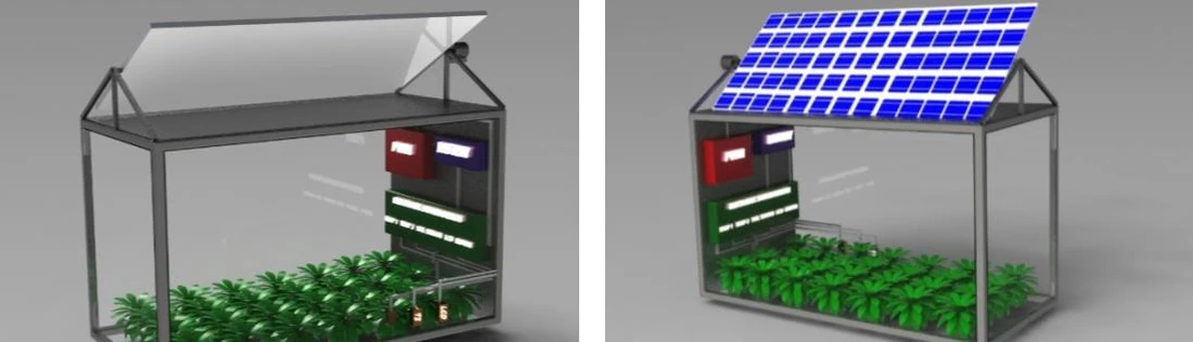
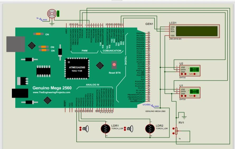
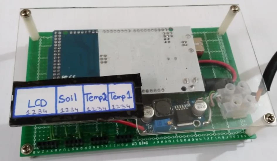
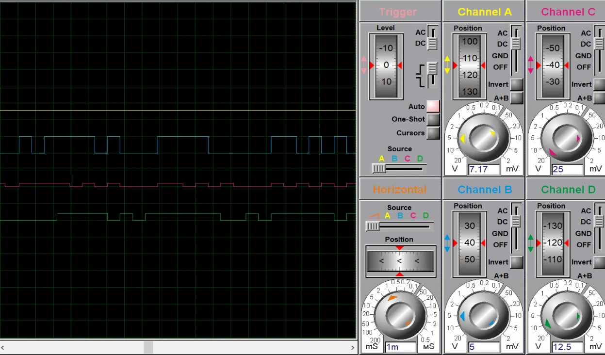
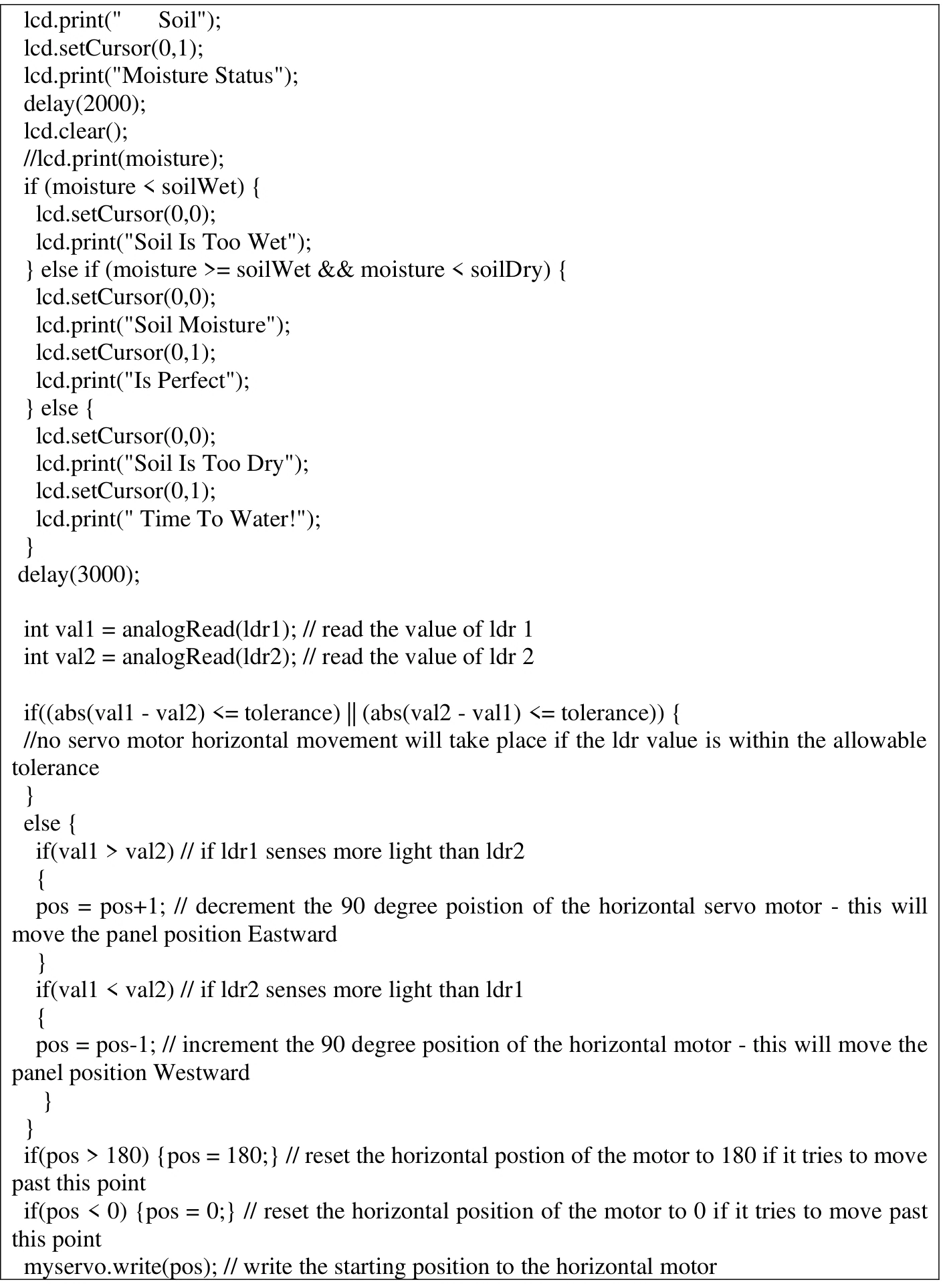
This project explores a compact agrivoltaic system in which solar generation and crop monitoring share one structure. It connects an Arduino Mega controller with two temperature and humidity sensors, a soil-moisture input, light-dependent resistors, a servo and an I2C character display. The report documents the work at several levels: an AutoCAD model describes the physical arrangement, a Proteus circuit shows the electronic connections, a prototype photograph records the controller assembly, and an Arduino appendix exposes the operating logic. The firmware reads indoor and outdoor conditions, reports soil status against two configured thresholds and compares east and west light readings to adjust the panel angle. A tolerance prevents unnecessary servo movement, while software bounds keep the commanded position within its stated range. The source also includes oscilloscope traces from the simulation and a wider discussion of irrigation, power storage and future agricultural deployment. The strongest demonstrated contribution is the integration of sensing, display and tracking within a single embedded workflow. Two overlapping report versions are treated as one project. The available evidence does not establish measured improvements in crop yield, water consumption or energy production; those remain motivations and proposed evaluation goals. Irrigation is described in the system concept, while the supplied firmware directly demonstrates soil-status messaging rather than a complete pump-control routine.
The engineering challenge
Integrate crop-condition monitoring and light-driven panel positioning while coordinating multiple sensor interfaces, display updates and servo limits.
Engineering approach
- Model the solar-panel structure and growing area in AutoCAD to communicate component placement.
- Build an Arduino Mega circuit in Proteus with environmental sensors, soil input, light sensors, servo and LCD.
- Read two DHT22 channels and an analog soil-moisture signal, then cycle through status messages.
- Compare two light-sensor readings and adjust servo position outside a configured tolerance.
- Document the physical controller assembly and simulated signal waveforms, distinguishing demonstrated functions from wider agricultural goals.
Results & observations
The supplied firmware reads separate indoor and outdoor temperature/humidity channels on digital pins 8 and 9.
Configured raw analog thresholds in the code for wet, intermediate and dry status; these are settings, not validated moisture percentages.
Software bounds for the servo command; initial position is 90° and the light-reading tolerance is 20 raw counts.
I2C display cycles through indoor, outdoor and soil-condition messages.
Features & capabilities
- Environmental sensing
- Soil-status classification
- Differential light tracking
- Servo position bounds
- I2C display interface
- CAD and circuit simulation
Software & engineering tools
Arduino IDE, Arduino Mega 2560, Proteus, AutoCAD, Arduino C/C++