Project brief
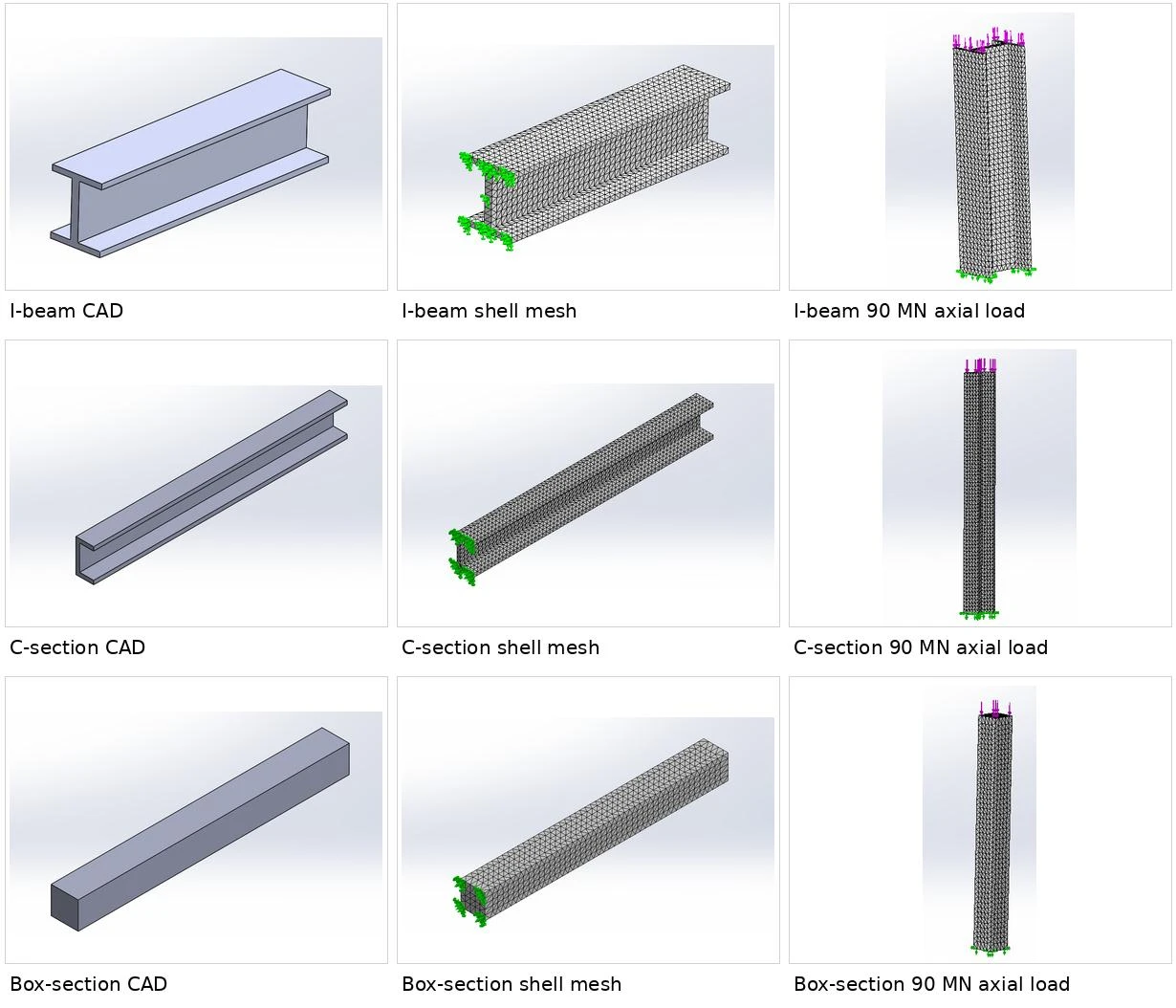
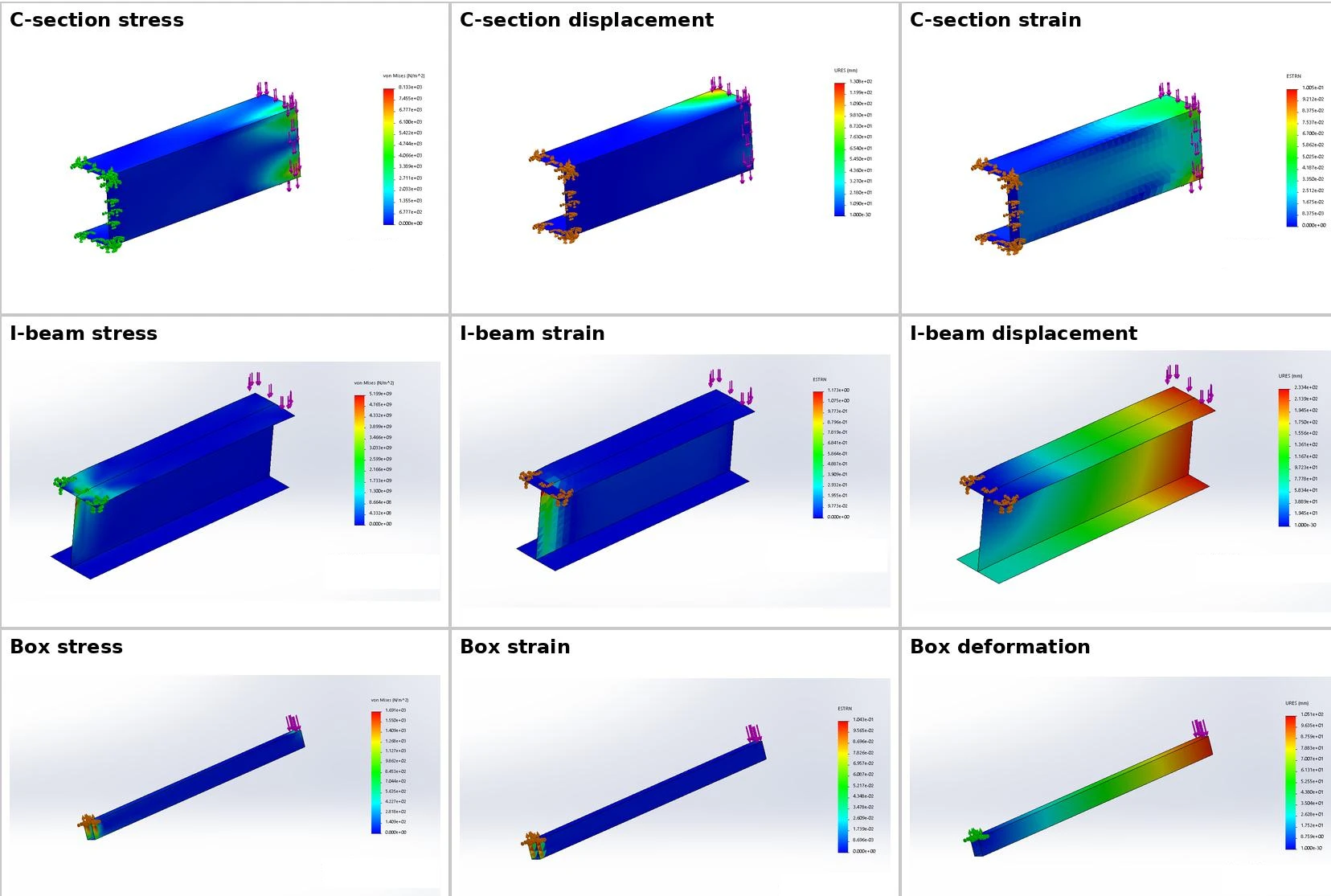
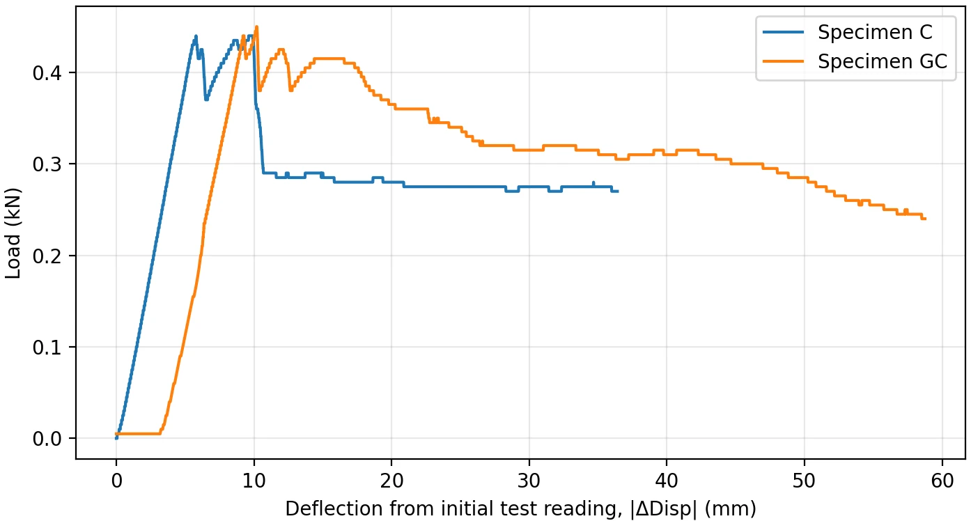
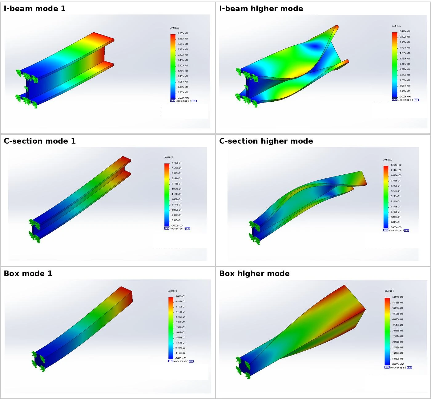
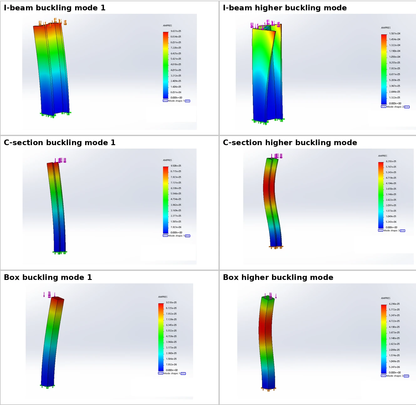
This project compares three aircraft-type thin-walled composite beam sections using a common SolidWorks Simulation workflow. I-beam, C-section and closed box geometries are represented with composite shell meshes and fixed-free boundary conditions. A carbon-fiber laminate supports the natural-frequency and eigenvalue-buckling studies, while a separate three-ply carbon/glass/carbon shell definition is used for the reported static-response assessment. The workflow connects geometry, orthotropic material properties, ply orientation, fixtures, loads and post-processing rather than treating the material as a single isotropic solid. Modal results compare the first five natural frequencies, and buckling factors are converted into critical loads using the stated reference compression. Static contour figures show how stress, strain and deformation vary across sections. An accompanying three-point-bending comparison checks beam-theory predictions against reported experimental measurements and explicitly reveals a larger discrepancy for one specimen. Under the modeled conditions, the I-beam leads the fundamental-frequency and buckling comparisons, with the box section intermediate and the C-section lowest. The report identifies mesh convergence, fixture singularities and more detailed ply-level failure output as future work, so the results remain a bounded simulation comparison rather than a certified structural design.
The engineering challenge
Compare open and closed composite sections consistently while separating material directionality, bending–torsion coupling, modal behavior, buckling stability and the limitations of experimental validation.
Engineering approach
- Model the I, C and box sections and create triangular composite shell meshes.
- Define orthotropic properties, laminate orientations and fixed-free boundary conditions.
- Run static response, natural-frequency and eigenvalue-buckling studies using the stated load cases.
- Convert buckling factors to critical loads and compare section rankings.
- Check three-point-bending predictions against reported specimen measurements and discuss remaining validation gaps.
Results & observations
Highest mode-one frequency of the three modeled sections; box 171.22 Hz, C-section 122.82 Hz.
Reported eigenvalue-buckling result under the 90 MN reference-load convention.
Three 0.3 mm plies: carbon at 0°, E-glass at 90° and carbon at 45°; 20 N end-load case.
Reported predicted-versus-experimental deflection errors for specimens C and GC, respectively.
Features & capabilities
- Three cross-section geometries
- Composite shell meshing
- Orthotropic laminate definition
- Static contour analysis
- Modal and buckling comparisons
- Bending-test validation discussion
Software & engineering tools
SolidWorks, SolidWorks Simulation, Composite shell elements, Eigenvalue analysis