Project brief
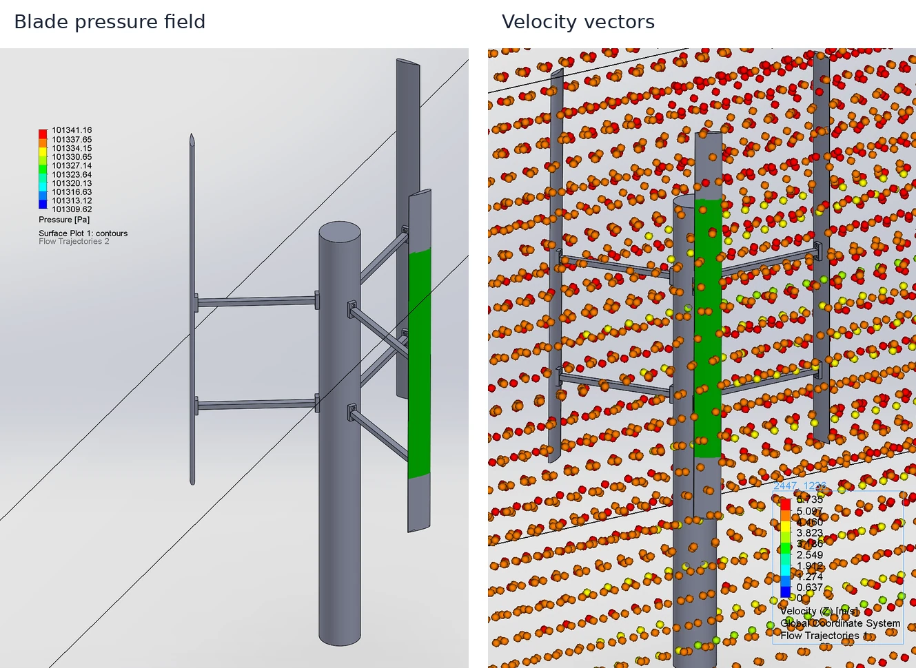
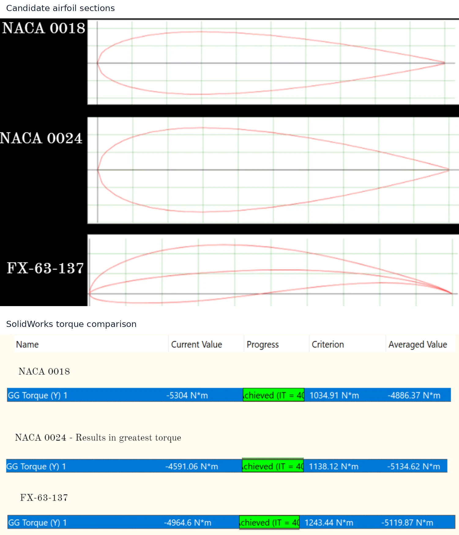
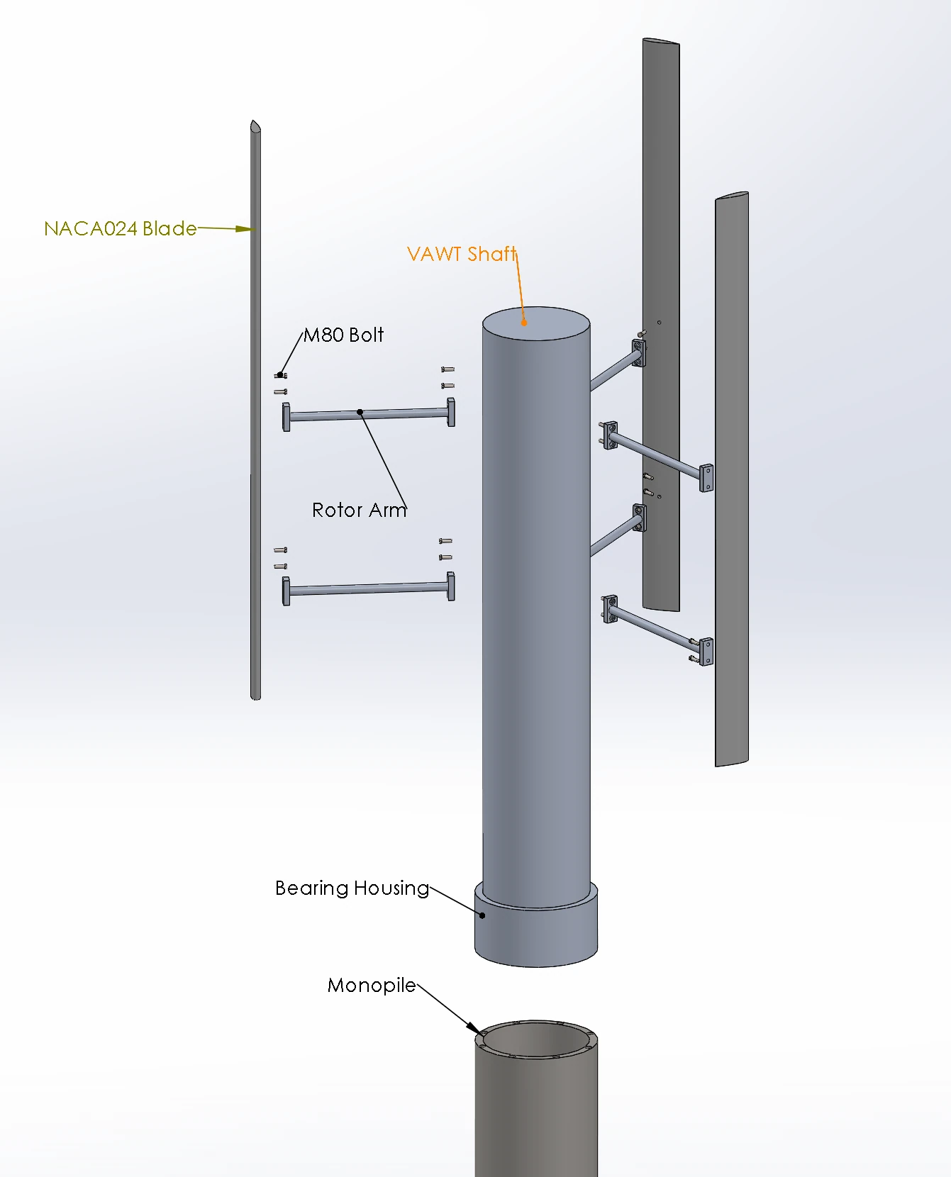
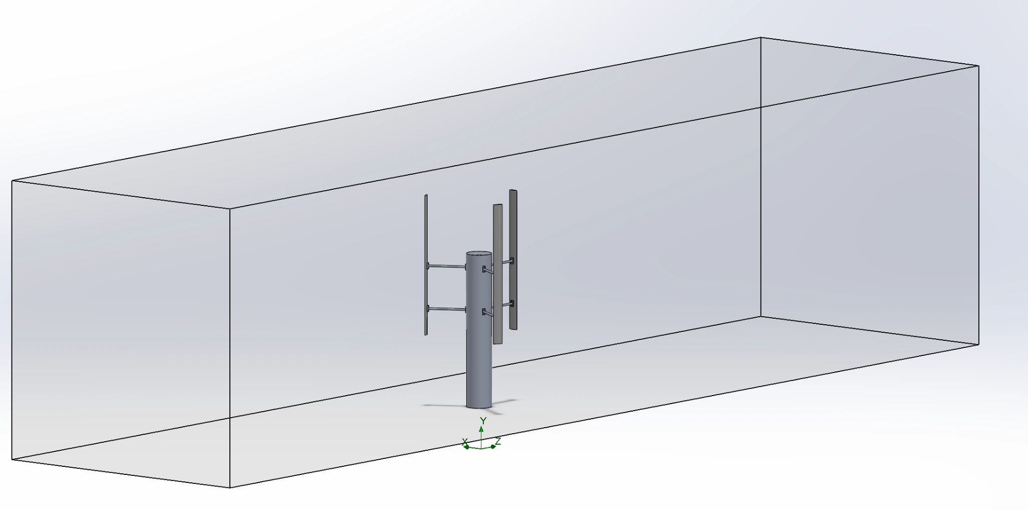
This project investigates a vertical-axis wind turbine concept for exposed bridge locations, using a three-blade H-rotor as the final design direction. The work connects site reasoning, turbine geometry, structural sizing and computational flow visualization. SolidWorks models define the shaft, rotor arms, blades, bearing housing and monopile connection, while an exploded assembly documents how the principal components fit together. The aerodynamic workflow compares NACA 0018, NACA 0024 and FX-63-137 sections in a modeled wind tunnel under a stated 5 m/s wind condition. Torque goals, pressure contours, velocity vectors and a solver trace provide several views of the same design decision. The source selects NACA 0024 because its reported averaged torque magnitude is the largest of the three candidates, although the comparison is close to FX-63-137. Aspect-ratio and solidity calculations then connect blade length and chord to the intended rotor size, and separate engineering calculations address shaft, support and connection loads. The report converts simulated torque and assumed operation into projected power and annual energy, but those estimates are not field production measurements. No mesh-convergence study or experimental aerodynamic validation is documented. The resulting portfolio case is a detailed CAD-and-CFD design investigation that shows the modeling sequence, comparison evidence and assumptions behind the proposed installation.
The engineering challenge
Select an airfoil and turbine geometry for multidirectional wind while making the flow-simulation comparison consistent with the mechanical assembly and the limits of an unbuilt concept.
Engineering approach
- Develop a three-blade H-rotor and its shaft, arms, bearing housing and monopile connections in SolidWorks.
- Create a wind-tunnel domain with specified inlet direction and 5 m/s flow conditions.
- Compare torque goals for NACA 0018, NACA 0024 and FX-63-137 blade sections.
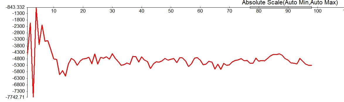
- Inspect pressure contours, velocity vectors and torque history to interpret the selected geometry.
- Connect blade aspect ratio and solidity to dimensions and perform shaft, tower and bolt sizing calculations.
Results & observations
NACA 0018, NACA 0024 and FX-63-137 are compared under the same reported flow condition.
The report’s stated standard simulation condition; not a long-term validated site model.
Its averaged torque magnitude is about 5.13 kN·m in the source comparison; the signed solver result is negative about the chosen axis.
The report combines an approximately 50 ft blade length with a 3.33 ft chord in its dimensional sizing.
Features & capabilities
- Three-airfoil comparison
- Wind-tunnel domain
- Torque-goal monitoring
- Pressure and velocity post-processing
- Exploded mechanical assembly
- Blade and support sizing
Software & engineering tools
SolidWorks, SolidWorks Flow Simulation, SolidWorks Motion Study, Engineering load calculations